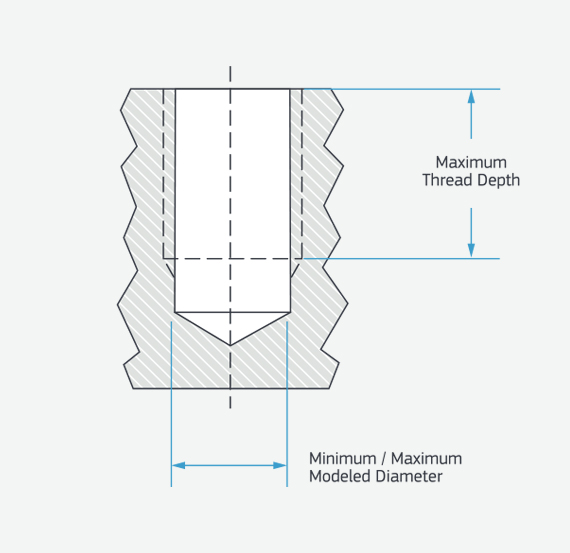
Threading: Standard Holes
UNC, UNF, and metric threads are available for standard holes on both milled and turned parts.
Milled Parts and Turned Parts (Aluminum and Brass)
| UNC threads | Minimum modeled diameter (in.) | Maximum modeled diameter (in.) | 75% hole drill size (in.) | Maximum thread depth (in.)* |
|---|---|---|---|---|
| #2-56 | 0.067 | 0.074 | 0.070 | 0.200 |
| #3-48 | 0.076 | 0.084 | 0.082 | 0.200 |
| #4-40 | 0.085 | 0.094 | 0.089 | 0.300 |
| #5-40 | 0.098 | 0.104 | 0.102 | 0.300 |
| #6-32 | 0.105 | 0.114 | 0.109 | 0.400 |
| #8-32 | 0.130 | 0.139 | 0.134 | 0.400 |
| #10-24 | 0.145 | 0.156 | 0.150 | 0.600 |
| #12-24 | 0.171 | 0.181 | 0.176 | 0.600 |
| 1/4-20 | 0.196 | 0.207 | 0.201 | 0.650 |
| 5/16-18 | 0.252 | 0.265 | 0.259 | 0.650 |
| 3/8-16 | 0.307 | 0.321 | 0.314 | 1.000 |
| 7/16-14 | 0.360 | 0.376 | 0.372 | 1.000 |
| 1/2-13 | 0.417 | 0.434 | 0.426 | 1.200 |
*Obstruction by other features of your part, lead-in treatments, or fixturing requirements may reduce the maximum depth of threads.
| UNF threads | Minimum modeled diameter (in.) | Maximum modeled diameter (in.) | 75% hole drill size (in.) | Maximum thread depth (in.)* |
|---|---|---|---|---|
| #2-64 | 0.069 | 0.075 | 0.072 | 0.200 |
| #3-56 | 0.080 | 0.084 | 0.083 | 0.200 |
| #4-48 | 0.087 | 0.098 | 0.093 | 0.300 |
| #5-44 | 0.100 | 0.104 | 0.104 | 0.300 |
| #6-40 | 0.111 | 0.119 | 0.115 | 0.400 |
| #8-36 | 0.134 | 0.142 | 0.138 | 0.400 |
| #10-32 | 0.156 | 0.164 | 0.160 | 0.600 |
| #12-28 | 0.177 | 0.186 | 0.182 | 0.600 |
| 1/4-28 | 0.211 | 0.220 | 0.215 | 0.650 |
| 5/16-24 | 0.267 | 0.277 | 0.272 | 0.650 |
| 3/8-24 | 0.330 | 0.340 | 0.335 | 1.000 |
| 7/16-20 | 0.383 | 0.395 | 0.389 | 1.000 |
| 1/2-20 | 0.446 | 0.457 | 0.451 | 1.200 |
*Obstruction by other features of your part, lead-in treatments, or fixturing requirements may reduce the maximum depth of threads.
| Metric threads | Minimum modeled diameter (mm) | Maximum modeled diameter (mm) | 75% hole drill size (mm) | Maximum thread depth (mm)* |
|---|---|---|---|---|
| M1.6 x 0.35** | 1.22 | 1.32 | 1.25 | 3 |
| M2 x 0.4 | 1.57 | 1.68 | 1.60 | 5.08 |
| M2.5 x 0.45 | 2.01 | 2.14 | 2.05 |
5.08 |
| M3 x 0.5 | 2.46 | 2.60 | 2.50 | 7.62 |
| M3.5 x 0.6 | 2.85 | 3.01 | 2.90 | 10.16 |
| M4 x 0.7 | 3.24 | 3.42 | 3.30 | 10.16 |
| M5 x 0.8 | 4.14 | 4.33 | 4.20 | 15.24 |
| M6 x 1.0 | 4.92 | 5.15 | 5.00 |
16.51 |
| M8 x 1.25 | 6.65 | 6.91 | 6.80 | 16.51 |
| M10 x 1.5 | 8.38 | 8.68 | 8.50 | 25.40 |
| M12 x 1.75 | 10.00 | 10.44 | 10.20 | 30.48 |
*Obstruction by other features of your part, lead-in treatments, or fixturing requirements may reduce the maximum depth of threads.
**Aluminum Only

Turned Parts (Steel, Stainless Steel, Titanium, and Copper)
| UNC threads | Minimum modeled diameter (in.) | Maximum modeled diameter (in.) | 75% hole drill size (in.) | Maximum thread depth (in.) |
|---|---|---|---|---|
| #4-40 | 0.085 | 0.094 | 0.089 | 0.300 |
| #5-40 | 0.098 | 0.106 | 0.102 | 0.300 |
| #6-32 | 0.105 | 0.114 | 0.109 | 0.400 |
| #8-32 | 0.130 | 0.139 | 0.134 | 0.400 |
| #12-24* | 0.171 | 0.181 | 0.176 | 0.500 |
| 1/4-20* | 0.196 | 0.207 | 0.201 | 0.500 |
*Threads must be centered on the axis of rotation
| UNF threads | Minimum modeled diameter (in.) | Maximum modeled diameter (in.) | 75% hole drill size (in.) | Maximum thread depth (in.) |
|---|---|---|---|---|
| #4-48 | 0.087 | 0.098 | 0.093 | 0.300 |
| #5-44 | 0.100 | 0.108 | 0.104 | 0.300 |
| #6-40 | 0.111 | 0.119 | 0.115 | 0.400 |
| #8-36 | 0.134 | 0.142 | 0.138 | 0.400 |
| #10-32 | 0.156 | 0.164 | 0.160 | 0.400 |
| #12-28* | 0.177 | 0.186 | 0.182 | 0.500 |
| 1/4-28* | 0.211 | 0.220 | 0.215 | 0.500 |
| 5/16-24* | 0.267 | 0.277 | 0.272 | 0.500 |
| 3/8-24* | 0.330 | 0.340 | 0.335 | 0.500 |
| 7/16-20* | 0.383 | 0.395 | 0.389 | 0.500 |
| 1/2-20* | 0.446 | 0.457 | 0.451 | 0.500 |
*Threads must be centered on the axis of rotation
| Metric threads | Minimum modeled diameter (mm) | Maximum modeled diameter (mm) | 75% hole drill size (mm) | Maximum thread depth (mm) |
|---|---|---|---|---|
| M3 x 0.5 | 2.46 | 2.60 | 2.50 | 7.62 |
| M3.5 x 0.6 | 2.85 | 3.01 | 2.90 | 10.16 |
| M4 x 0.7 | 3.24 | 3.42 | 3.30 | 10.16 |
| M5 x 0.8 | 4.14 | 4.33 | 4.20 | 10.16 |
| M6 x 1.0* | 4.92 | 5.15 | 5.00 | 12.70 |
| M8 x 1.25* | 6.65 | 6.91 | 6.80 | 12.70 |
| M8 x 1.0* | 6.91 | 7.16 | 7.01 | 12.70 |
| M10 x 1.25* | 8.64 | 8.92 | 8.79 | 12.70 |
*Threads must be centered on the axis of rotation