
Some engineers have difficulties properly designing sheet metal parts for manufacturing. That’s not you, of course (wink-wink). Still, we notice that there are certain issues that frequently appear in models that we’ve been asked to quote. With these issues in mind, we offer this list. It isn’t exhaustive, but strap yourself in and see what many of your colleagues do wrong when they design for sheet metal and submit an RFQ.
1. Using Completed 3D Models of a Part with no Bends
This is probably the most basic issue we see. Sheet metal is flat and must be bent, formed, cut, lased, and sometimes cajoled into its final shape. It’s a very hands-on process. If you design your sheet metal part as a solid object, it’s important that you send us a CAD file that appears folded, but shows where bends should go. Related to this, because the raw materials are single sheets of metal, the entire part must have the same material thickness throughout. For example, if you create a part that uses 0.125 in. (3.175mm) thick aluminum, your entire part will need to be that same thickness.
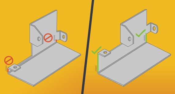
2. Placing Features too Close to Bend Lines
A quick way to create difficulties during manufacturing is to place holes, tabs, or other features too close to a bend. So, how close can you get? Just follow the 4T rule. Keep all features at least 4x material thickness away from bend lines. So, if your design tells us to use 0.050 in. (1.27mm) copper, give your feature at least 0.200 in. (5.08mm) of clearance. If you don’t, the part will deform awkwardly in the press brake, and no one wants that.
3. Designing Perfectly Perpendicular Sheet Metal Corners
When you bend sheet metal in a press brake, the resulting bend doesn’t form a perfect 90-degree angle. Instead, the tool has a rounded tip that adds a radius to the bend. If you measure the length of that bent area and divide it by two, you’ll get the bend radius, a figure that is defined by the tool that made it. If the size of that curve is important to you, make sure you specify it in your model.
The most common internal bend radius (and our default) is 0.030 in. (0.762mm). An important consideration to remember is that the external bend radius—the one formed on the die side of the press brake toolset—is equal to the material thickness plus the internal bend radius.
Some designers like to get fancy and create different radii for each bend in a part. Want to save some money? Use the same radius for all of the bends. When your manufacturer doesn’t have to change tooling that saves you on labor costs.
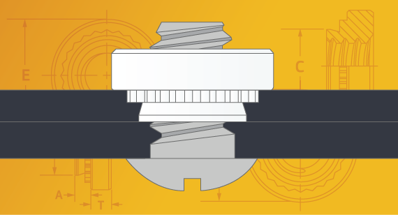
4. Forgetting to Include Detailed Hardware Specs in your CAD File
Do you know of anyone who wants longer lead times? Probably not. Always remember to let your manufacturer know what kind of hardware you want to use by including the details in your top level assembly information. Whether it’s a self-clinching nut like CLS-440-2, flush-head stud like FHS-M5-15, or other hardware, this guarantees that you’ll get exactly what you want placed in the location you expect it. To save yourself time and trouble, download and use the PEM clinch hardware models.
5. Picking the Wrong Finish (or Not Using One When You Need One)
Generally, finishes serve two purposes. They can protect your part or they can make it look better. Some do both. Aesthetic finishes—ones that focus on looks—don’t focus on corrosion protection. Still, powder coating does offer some protection (unless a scratch reaches to the metal beneath). Silk screening, on the other hand, is used to add text and images to parts and offers no protection at all.
Chemical conversion finishes are meant to protect your parts by altering the properties of the outermost layers. For example, if you want to use steel in a corrosive environment, consider choosing galvanized or galvannealed metal, which already has a protective zinc coating. Watch out, though! We can’t weld galvannealed steel due to the dangerous toxins it would give off. Instead, we can make the parts out of steel and add a zinc coating after welding.
Chromate conversion can give your part electrical connectivity and provides a primer layer to your part if you want to paint. Anodizing can add a pop of metallic color to your parts while also protecting them. Think of that colorful, small flashlight you own.
Here’s a helpful summary of the most common finishes for sheet metal.
6. Selecting the Wrong Sheet Metal for the Job
Imagine making hundreds of parts out of unfinished steel that are destined for installation in a salty, marine environment. Amazingly, we’ve seen quotes that request just that. Save yourself the grief of the customer complaints you’ll get when your parts corrode and consider these factors when selecting the right sheet metal:
- Expected wear on your part from daily use
- Corrosion protection
- Manufacturability
- Cosmetic appearance
- Mechanical properties (tensile strength, yield strength, ductility, etc.)
- Conductivity (for electrical applications)
This handy chart can help.
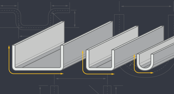
7. Failing to Consider U-Channel Strength
When designing U channels, always think about the strength of the material you’re using and how easily it can bend. At Brazil Metal Parts, narrower doesn’t work for us because of our tooling. If we had narrower tooling, we could manufacture narrower U channels. The bottom line is that it is best practice when working with us to maintain at least a 2:1 width-to-height ratio for your U channels. If you need a narrower channel, consider a welded or riveted assembly.
8. Designing Unrealistic Weld Requirements
Have you ever tried welding a seam inside a closed box? Nope? Neither have we. Make sure that your weld requirements are realistically achievable. It’s important to remember that if a welding torch can’t access a seam, the weld can’t happen. We strongly recommend designing so all welds are done on the outside of the part.
Metal melts under high temperature, so you need material thicknesses that can manage the extreme heat. The minimal material thickness for welding is 0.040 in. (1.016mm) to ensure that the weld doesn’t end up an unholy mess of melted metal.
Finally, in your models, always indicate the need for welds using a welding function or nomenclature. Never box corners to indicate welding.
No single design tip can cover all the sheet metal mistakes we’ve seen, but this “best of” collection is a start. Take a look at our sheet metal design guidelines to keep you moving in the right direction.
For additional help, feel free to contact a Brazil Metal Parts applications engineer at +86-755-29729151 or [email protected]. To get your next design project started today, simply send a 3D CAD model to us for an interactive quote within hours.