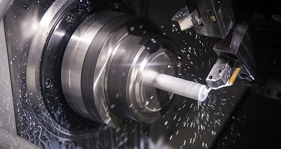
Design Guidelines: CNC Turning
Our basic guidelines for CNC turning include important design considerations to help improve part manufacturability, enhance cosmetic appearance, and reduce overall production time.
Size
Maximum Dimensions
| Diameter for Steel, Stainless Steel, and Titanium | 2.95 in. |
|---|---|
| Diameter for Aluminum and Brass | 3.95 in. |
| Length | 9 in. |
| Diameter for Steel, Stainless Steel, Titanium, and Copper | 74.93mm |
|---|---|
| Diameter for Aluminum and Brass C360 |
100.33mm |
| Length | 228.6mm |
Minimum Dimensions
| Diameter | 0.16 in. |
|---|---|
| Length | 0.05 in. |
| Wall Thickness | 0.020 in. |
| Angle | 30° |
| Diameter | 4.07mm |
|---|---|
| Length |
1.27mm |
| Wall Thickness |
0.51mm |
| Angle |
30° |
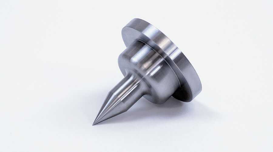
Small features may be allowed, but the diameter in any region should not be less than 0.030 in. (0.76mm). Sharp conical points are allowed; angles should be greater than 30 degrees. Walls thinner than 0.020 in. (0.5mm) typically do not survive the machining process. For specific turning dimensions by material, see maximum part extents for machining.
Typically, Brazil Metal Parts can maintain a machining tolerance of +/- 0.005 in. (0.13mm).
Live Tooling Capabilities
Our lathe machines contain live tools that allow additional milled features to be added to turned parts including flats, slots, and grooves. We can also add on-axis, axial, and radial holes to turned parts, but only support holes that are either parallel or perpendicular to the axis of revolution, and we cannot accommodate holes at odd angles for hard metals. We can mill off-axis holes on turned parts machined from aluminum or brass.
CNC Machining Surface Finish Guide
Get a realistic snapshot of the surface finishes that are possible on machined plastic and metal parts.
DOWNLOAD >
Design Essentials for CNC Machining
We've compiled some of our best design tips to help you optimize your part design for CNC machining.
DOWNLOAD >
Materials
- Aluminum
- Brass
- Low Carbon Steel
- Steel Alloy
- Stainless Steel
- Titanium
Surface Finishes
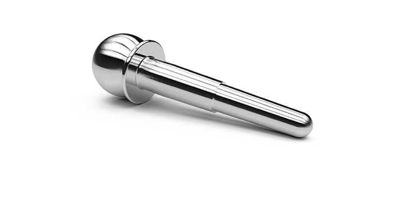
Parts that are turned typically have a very smooth surface finish. The as-machined surface finish of the cylindrical areas will typically be much smoother using the lathe than the mill, so consider this when selecting the machining method for those parts that qualify for either method. Areas cut with live tooling, such as flats and slots, may have visible tools marks. If desired, the metal parts can be lightly bead blasted leaving a fine matte finish. Hard metals like steel and stainless steel can also have edges broken (deburred) with a light bead blast to remove metal slivers, and sharp or rough areas.
| ALUMINUM | Edges broken with visible toolmarks, edges broken with light bead blast, or sharp edges with visible toolmarks |
|---|---|
| ALL OTHER METALS | Edges broken with visible toolmarks or edges broken with light bead blast |
Threaded Holes
We currently support UNC and UNF threads from #2 up to 0.5 in., and metric threads from M2 to M12. Avoid modeling internal threads on your part design.
Radii
Sharp inside corners on a part will be radiused (rounded) as a natural result of the CNC machining process. Resulting radii will be identified before the part is milled. Turned outside corners will typically include a 0.005 in. chamfer.
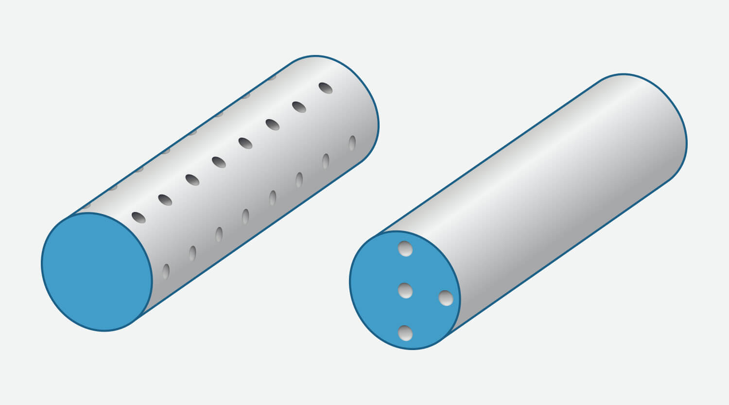
Holes and Grooves
We can add on-axis, axial, and radial holes to turned parts, and we support holes that are either parallel or perpendicular to the axis of revolution. Off-axis holes are supported for turned parts machined from aluminum and brass.
Text on Parts
Text is not supported on turned parts at this time.
Minimum hole size:
- On-axis and axial: 0.04 in. (1mm)
- Radial: 0.08 in. (2mm), 0.04 in (1mm) for aluminum and brass
Grooves:
- Minimum OD groove width: 0.047 in. (1.2mm)
- Minimum OD groove width for aluminum and brass:0.019 in (0.5mm)
- Maximum OD groove depth: 0.95 in. (24.1mm)—varies with groove width
- ID grooves are not supported at this time

Free DFM analysis within hours
GET A QUOTERequest More Information
Thanks! We’ve received your message and a member of our team will be in touch with you shortly.
You can find more information about Brazil Metal Parts here:
Thanks for your interest in Brazil Metal Parts. Please let us know how we can provide more information on our services. Once we receive your comments, an applications engineer from our team will follow-up as soon as possible.
If you have a 3D CAD model of your part ready, upload it online now to receive an interactive quote with free design for manufacturability feedback within hours.