Threaded Holes Guidelines
Our CNC machining service provides the ability to easily add threaded features to milled and turned parts. Threads are specified within our automated interactive quotes. When a quote is returned, the 3D display will show which thread types are possible for each feature. Different threads (where possible) or no threads can be selected on a feature-by-feature basis. View a sample quote to explore a 3D model with threads.
For those having trouble with the interactive display, a 3D PDF is included in the demo quote that shows the thread options available. After an order is placed, an order confirmation will be emailed with the thread sizes selected. Please review the order confirmation for accuracy.
Milled vs. Turned Parts
We offer a limited selection of UNF, UNC, and metric threads for machining along with coil and key inserts (but do not supply or install the inserts). On both milled and turned parts, threaded holes must be modeled at the proper diameter, however, threading options differ for milled and turned parts. Automatic external threads are not available for milling at this time. It is possible to machine approximate external threads using ball and flat end mills if threads are modeled and are at least 1/2 -13 (M12) or larger. Threaded holes on turned parts are also available and external threads are offered on the axial diameters. Simply model the nominal diameter; do not model the threads.
All of our available selections are listed in the guide below. If you have any issues or questions please contact an applications engineer at [email protected] or +86-755-29729151.
| THREADING CONSIDERATIONS |
|
| THREADING: MAXIMUM REACH | |||
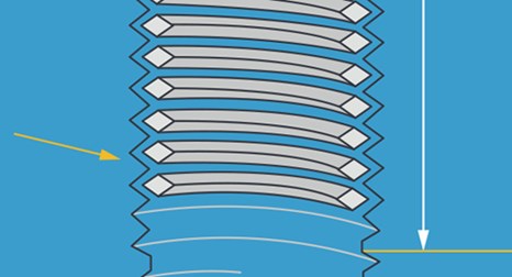
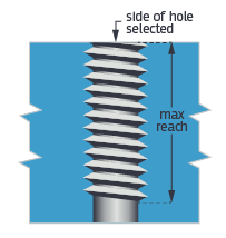
Example 1:This is a cross-section view of a through hole that is threaded from one side. In this case, the hole depth exceeds the reach of the tool. The result is an unthreaded section that is opposite the side selected. |
 |
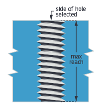
Example 2:This is a cross-section view of a through hole that is threaded from one side. In this case, the hole depth does not exceed the reach of the tool. The result is the threads will be formed across the entire length of the hole. |
 |
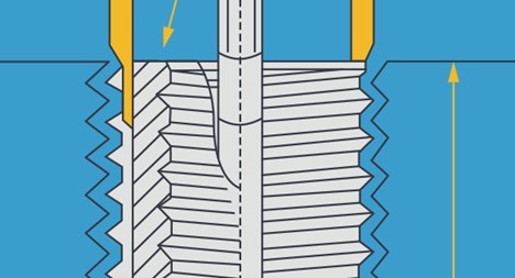
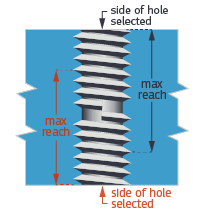
Example 3:This is a cross-section view of a through hole that is threaded from two sides. In this case, the hole depth is too long to reach from one side only. However, it can be reached past the center from either side. If this hole is selected to be threaded from both sides, there will be a discontinuity in the middle of the hole. This means that a bolt can only be threaded to roughly half the depth of the hole. |
 |
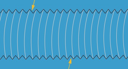
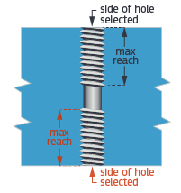
Example 4:This is a cross-section view of a through hole that is threaded from both sides. This is similar to Example 3, but the hole is longer and the tool can not reach to the center from either side. In this case, the hole will be threaded to the maximum reach from both sides, leaving an un-threaded section in the middle. |
 |
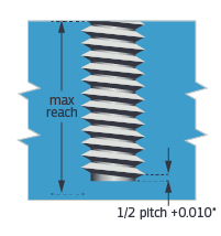
Example 5:This is a cross-section view of a blind hole (a hole that has a bottom/doesn’t pass through the part). In this case, the hole is less than the full reach and threading will stop roughly 0.010 in. off the bottom. If the hole is deeper than the tool can reach, threads will be cut as deep as possible. |
 |
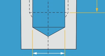
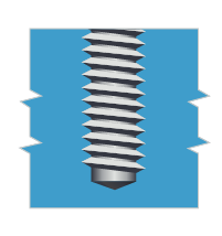
Example 6:A designer may add a point at the bottom of a blind hole. In most cases, this represents the point left if a pilot hole is drilled with a drill bit. It may also serve a function to their design, or provide an area for chips that are generated during the threading process to fall. If this point is added to the model, the threading will stop roughly 0.010 in. above the start of the point angle. |
 |