
Sharp corners have their place. Without them, we wouldn’t have triangles, all birthday cakes would be round, and it’d be darned tough to scrape a piece of gum off your shoe. But sharp corners can spell trouble when injection molding plastic parts, and product designers should be aware of the pitfalls associated with “being square” when developing their wares—without the right amount of corner rounding and filleting, part accuracy, strength and aesthetics suffer. Smooth, rounded edges are important, but there are several other factors that can impact even a well-radiused part design. These include:
- Material selection. Some plastics are more forgiving of sharp-cornered parts. Choosing the right one for your application is a necessary step towards accurate, functional parts.
- Wall thickness. Beefing up adjacent walls may absorb some of the stress associated with sharp internal corners, but can, in turn, create other design challenges.
- Part geometry. Some parts are simply more “moldable” than others. Achieving proper form, fit and function depends on sound part design, a large piece of which is appropriate corner radii.
Despite its widespread use across nearly every industry, injection molding is a complex process. The considerations listed above impact the amount of corner radius required in any given part design, and whether it will be effective. This design tip will help you achieve a Goldilocks balance of each.
The Right Radius
Imagine you’re designing an injection-molded case used to carry small servo motors and similar components for an electronics manufacturer. The first design iteration delivers a shallow, compartmentalized case similar to a tackle box, one with a series of large, square-cornered compartments to keep the contents from shifting during transport. The motors are fairly heavy for their size, so you select a tough, glass-filled nylon material for the body and, because you want to view the container’s contents without unbuckling the cover, transparent acrylic for the lid.
Unfortunately, the case comes back unusable. The bottom is warped and the walls of each compartment are so buckled that the motors either don’t fit or shift around enough to cause damage. That’s because the case design contains sharp corners that generate stress during the molding process.
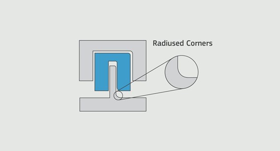
There are two types of radius to consider: internal and external. Fillet radii are those found at the bottom of each compartment, where the walls intersect the floor. Rather than leaving these corners sharp, a radius equal to at least 0.5 times the adjacent wall thickness should be used.
Similarly, the radii at the tops of those walls would be rounded to three times that amount, or 1.5 times the thickness of the nearest wall. This allows molten plastic to flow more easily, and eliminates the residual stress that twists thin-walled workpieces. It also helps prevent cracking, which leads to premature product failure.
Material Selection
You might also see gaps along the tops of some of the compartments, or at the outside perimeter of the case, as though there weren’t enough plastic available to complete the part. Proper corner radii often help in this case, but the culprit could be the raw material.
When forced through the intricacies of an injection mold, molten plastic does not behave like an amorphous, easygoing blob. It contains long chains of molecules that create links with adjacent molecules, and thus resist being crammed into tight corners, or having to flow around sharp features such as posts and wall intersections. The result is often a short shot, a situation where the material is unable to reach every nook and cranny of the mold cavity, leaving gaps in the finished product.
Even when the material does flow completely, the residual stress caused by all that molecular bending and twisting manifests itself as warp and bow in the molded part, especially with improperly designed corners. This is especially true for glass- and fiber-filled materials, as the greater strength and molecular integrity of these materials makes them less amenable to “going with the flow” than unfilled plastics. Changing to a different or unfilled plastic might help, but without the right mold design, part warp is a concern even with free flowing materials like TPU and TPE (santoprene). Again, proper radiusing goes a long way to avoid these issues.
Manufacturing Methods
You should also recognize that machining limitations may cause these recommendations to fall by the wayside, because unless alternative manufacturing methods are used, the internal corners in any mold cavity cannot be smaller than the radius of the endmill used to machine them, a consideration your Brazil Metal Parts quote will clearly illustrate.
What are these manufacturing methods? Let’s consider another mold design, this one for an insulator sleeve for a finger length medical device. The “male” part of the mold is an aluminum insert that resembles a popsicle shape, with gentle curves and tapers that are simple to machine and make for easy part ejection. The female portion of the mold—the piece that will form the outside of the insulator sleeve—is also injection molding-friendly, but unfortunately is challenging to produce via conventional methods due to its depth and narrow cross section.
That’s not to say it can’t be done, just that it will cost a bit more. Electrical discharge machining, or EDM, is a non-contact process that uses high-energy sparks to erode or “burn” away metal, and is often used to create features that cannot be otherwise machined. It requires electrodes, tools typically made of graphite or copper alloy that have been machined in the inverse shape of whatever feature is being burned. Both the electrode and the workpiece are worn away during EDM process (although electrodes erode far more slowly) making it necessary to machine a series of tools to complete most jobs.
Mold cavities such as this are quite easy to EDM, but all of that arcing, flushing and orbiting makes it prohibitively slow for most quick-turn molding scenarios. This is why many moldmakers, Brazil Metal Parts included, fabricate bolt-on inserts to produce difficult part geometries. For our medical device example, the taper sections and the bullnose of the female section would likely be milled on a CNC machining center and bolted into a square pocket in the female portion of the tool, also constructed using assembled components. And for the electronics carrying carrying case, the pockets would probably be formed by using bolt-on chunks of aluminum with narrow channels in between, forming a checkerboard pattern through which molten plastic can flow. In both scenarios, proper radii (and draft angles) should be applied throughout the different mold components, assuring part integrity and easy part ejection.
Part Geometry
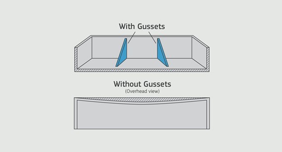
Many parts benefit from a good ribbing. Take a thin, flat piece of polypropylene or ABS plastic and give it a twist. Pretty easy, huh? To improve the strength of plastic parts, designers will often increase wall thicknesses. This can lead to part sink, shrink and bubbles, however, and should be avoided. A better alternative is the introduction of a honeycomb pattern on thin cross-sections, or a series of short vertical ribs aligned in the direction of the part’s bending forces. This makes plastic parts stiffer and greatly increases their structural strength—with the servo motor case, the base and lid of the product should be ribbed to make it strong yet lightweight, and its contents protected against every possible misfortune. Just remember that all of those rib corners—both inside and out—should be radiused appropriately.
If all that rounding and filleting sounds like a hassle, don’t worry; most CAD systems make short work of such tasks. And Brazil Metal Parts will help by highlighting potential problem areas in the quote’s design for manufacturability (DFM) section.
It’s also important to recognize that design rules like the ones described here are made to be broken—raw material, part size, feature geometry and production quantity all have a role to play in part design, which is one reason why a thorough DFM analysis and advice from someone knowledgeable in this area is an important step in any injection molding project.