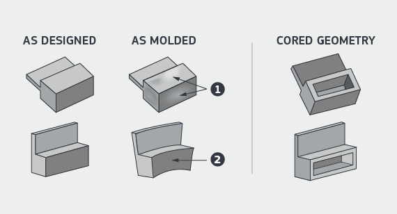
- Wall Thickness
- Cored Geometry
- Recommended Wall Thickness
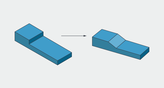
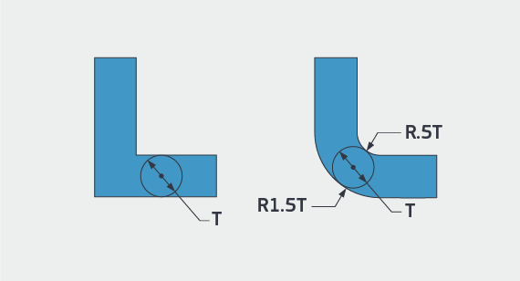
- Ramps and Fillets
- Sharp Corners
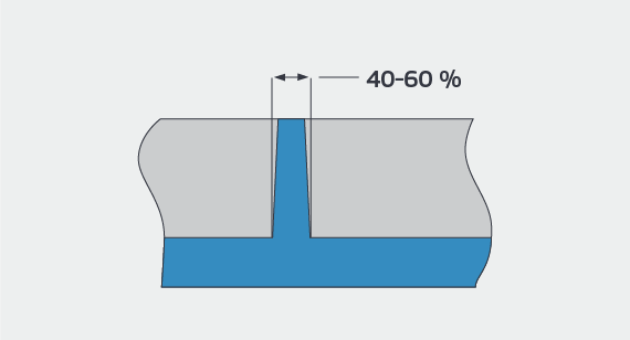
- Ribs
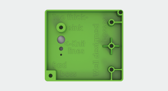
- Bosses
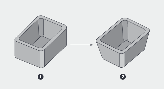
- Draft
- Core-cavity
- Deep Milling
- Undercuts
- Sliding Shutoffs
- Side Actions
- Bumpoffs
- Pickouts
- Steel Core Pins
- Text
- Tab Gates
- Self-Mating Parts
- Tolerances
- Choosing a Material
- Selecting Colors
- Resin Additives
Designing plastic parts for moldability has always been important for traditional injection molding processes, but it’s particularly beneficial during Shunjing injection molding to ensure speed and quality remain constant during manufacturing. This guide examines many of the important design considerations that are encountered during injection molding part design and product.
What is Shunjing Injection Molding?
Shunjing injection molding a technology-driven process that leverages manufacturing automation. CAD models are sent directly to the production floor where mold milling begins, but in most cases, molds are fabricated from aluminum, not steel. This allows for faster and most cost-effective tooling when compared to traditional steel molds.
There are number of surface finish options available and capabilities include side-action and hand-load inserts as well as simple overmolding and insert molding. Selective use of electrical discharge machining (EDM) is applied to improve mold features like corners and edges. The result is part production within a few weeks versus months when compared to traditional injection molding methods.
Here are some applications that work well for Shunjing injection molding and some industries taking advantage of the technology:
Common Applications for Injection Molded Parts
- Iterate quickly with quick-turn prototypes
- Test functionality during product development with production-grade parts
- Test multiple materials
- Test multiple CAD models
- Make quick iterations
- Implement bridge tooling
- Leverage low-volume production for on-demand parts
- Manage demand volatility
- Get thousands of parts within days
Industries Leveraging Injection Molding
- Medical and health care
- Automotive
- Electronics
- Aerospace
- Unmanned aerial vehicles (UAVs)
- Consumer products
- Appliance
- Lighting
- Marine
- Robotics
From wall thickness and radii to ramps and ribs, let’s look at all of the factors designers and engineers should consider if their parts will be injection molded.
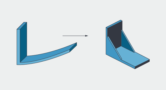
Wall Thickness
The most important design requirement for getting good molded parts: maintain constant wall thickness. Good injection-molded part design relies on consistent wall thickness to minimize the potential for warped or distorted parts.
Size
Maximum Dimensions
| SIZE | 18.9 in. x 29.6 in. x 8 in. |
|---|---|
| VOLUME | 59 cu. in. |
| DEPTH | 4 in. from parting line |
| Up to 8 in. if parting line can pass through the middle of the part | |
| PROJECTED MOLD AREA | 175 sq. in. |
| SIZE | 480mm x 751mm |
|---|---|
| VOLUME | 966,837 cu. mm |
|
DEPTH |
101mm from parting line |
| Up to 203.2mm if the parting line can pass through the middle of the part | |
| PROJECTED MOLD AREA | 112,903 sq. mm |
Wall Thickness Guidelines
| MATERIAL | RECOMMENDED WALL THICKNESS |
|---|---|
| ABS | 0.045 in. - 0.140 in. |
| Acetal | 0.030 in. - 0.120 in. |
| Acrylic | 0.025 in. - 0.500 in. |
| Liquid Crystal Polymer | 0.030 in. - 0.120 in. |
| Long-Fiber Reinforced Plastics | 0.075 in. - 1.000 in. |
| Nylon | 0.030 in. - 0.115 in. |
| Polycarbonate | 0.040 in. - 0.150 in. |
| Polyester | 0.025 in. - 0.125 in. |
| Polyethylene | 0.030 in. - 0.200 in. |
| Polyphenylene Sulfide | 0.020 in. - 0.180 in. |
| Polypropylene | 0.035 in. - 0.150 in. |
| Polystyrene | 0.035 in. - 0.150 in. |
| Polyurethane | 0.080 in. - 0.750 in. |
| MATERIAL |
RECOMMENDED WALL THICKNESS |
|---|---|
|
ABS |
1.143mm - 3.556mm |
| Acetal |
0.762mm - 3.048mm |
| Acrylic | 0.635mm - 12.7mm |
| Liquid Crystal Polymer | 0.762mm - 3.048mm |
| Long-Fiber Reinforced Plastics | 1.905m - 25.4mm |
| Nylon | 0.762mm - 2.921mm |
| Polycarbonate | 1.016mm - 3.81mm |
| Polyester | 0.635mm - 3.175mm |
| Polyethylene | 0.762mm - 5.08mm |
| Polyphenylene Sulfide | 0.508mm - 4.572mm |
| Polypropylene | 0.635mm - 3.81mm |
| Polystynene | 0.889mm - 3.81mm |
| Polyurethane | 2.032mm - 19.05mm |
Note: These are general guidelines, subject to part geometry and molded construction. Larger parts shouldn't be designed with the minimum wall thickness. Brazil Metal Parts’ general rule for wall thickness is 0.040 to 0.140 inches.

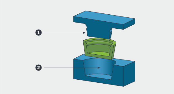
Core-cavity
When you draft, use core-cavity instead of ribs if you can. It allows you to have constant wall thickness rather than walls with a thick base. We can mill molds with better surface finish and deliver better parts faster.
Deep Milling
Draft the part as much as possible. This allows us to make deeper features for you. Draft allows us to reduce tool chatter and cosmetic defects when milling deep walls. If you can fit it in, use 1 degree of draft or more. On core-cavity designs, try to use 2 degrees or more. A rough rule of thumb is 1 degree of draft for each of the first 2 inches of depth. From 2 to 4 inches of depth, either 3 degrees of draft or a minimum of 1/8 in. thickness may be required.
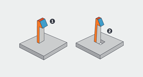
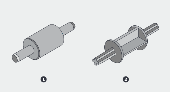
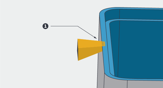
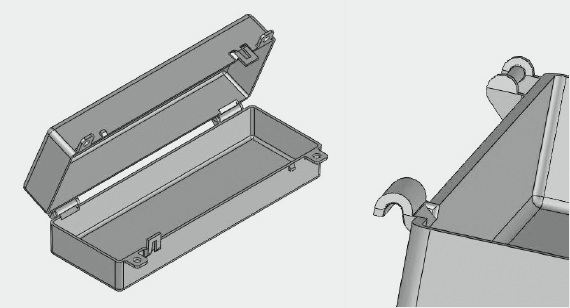
Undercuts
An undercut is an area of the part that shadows another area of the part, creating an interlock between the part and one or both of the mold halves. The left image (1) illustrates a clip with undercut feature. On the right image (2), an access hole beneath the undercut allows the mold to protrude through the part and provide the needed latch shutoff geometry.
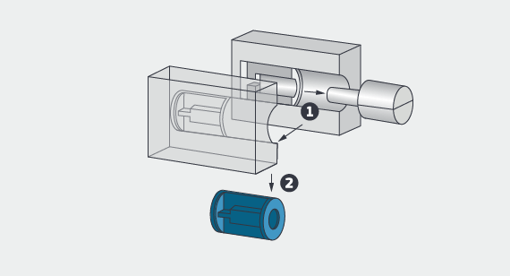
Pickouts
A pickout is a separate piece of metal that is inserted into the mold to create an undercut. It is ejected with the part, then removed by the operator and re-inserted in the mold. Using a pickout overcomes many shape and positioning restrictions, but is more costly than sliding shutoffs, or using a side-action.
Steel Core Pins
These holes can be made with steel core pins in the mold. A steel pin is strong enough to handle the stress of ejection and its surface is smooth enough to release cleanly from the part without draft. There shouldn’t be any cosmetic effect on the resulting part; if there is, it will be inside the hole where it won’t be seen.
Logos and Text on Parts
Textured surfaces, molded part numbers, and company logos look cool, but be prepared to pay a bit extra for these and other non-mission critical features. That said, permanent part numbers are a requirement for many aerospace and military applications.
- Use a mill-friendly font such as Century Gothic Bold, Arial, or Verdana (san-serif fonts)
- Keep it above 20 pt.
- Don’t go much deeper than 0.010 to 0.015 inches
- Be prepared to increase draft if part ejection is a concern
Tolerances
- We can hold about ±0.003 in. machining accuracy.
- Shrink tolerance depends mainly on part design and resin choice. It varies from 0.002 in./in. for stable resins like ABS and polycarbonate to 0.025 in./in. for unstable resins like TPE.
- There are techniques for getting the most accuracy out of our process. Please contact an applications engineer at +86-755-29729151 or [email protected].
Material Selection
When choosing a material for your part, relevant properties might include mechanical, physical, chemical resistance, heat, electrical, flammability or UV resistance. Resin manufacturers, compounders and independent resin search engines have data online. For data sheets to materials that Brazil Metal Parts carries, visit brazilmetalparts.com/materials/. Here are a quick look at some common commodity and engineering resins.
Commodity Resins
Polypropylene
- Soft
- Tough
- Cheap
- Chemical resistant
- Makes good living hinges
Polyethylene
- Soft
- Tough
- Cheap
- Chemical resistant
- High Density
- Low Density
Polystyrene
- Hard
- Clear
- Cheap
- Brittle but can be toughened
Engineering Resins
ABS
- Inexpensive
- Impact Resistant
- Equipment and handheld housings
- Susceptible to sink
Acetal
- More expensive
- Strong
- Good lubricity and machinability
- Very sensitive to excess wall thickness
LCP
- Very expensive
- Very strong
- Fills very thin parts
- Weak knit lines
Nylon
- Reasonable cost
- Very strong
- Susceptible to shrink and warp, particularly glass-filled
- Absorbs water - dimensional and property change
Polycarbonate
- Moderate cost
- Very tough
- Good dimensional accuracy
- Susceptible to chemical stress cracking, voids
PBT, PET, PPS, PSU, PES, PEI, and many others
Selecting Colorants
We offer custom color matching at Brazil Metal Parts in addition to offering a 3 percent salt/pepper mixture for most stocked, re-compounded material, or customer-supplied colorants.
Stock colors from the resin vendor are typically black and natural. Natural might be white, beige, amber or another color. Semi-custom colors are created when colorant pellets are added to natural resins. For available colors, visit our materials page. There is no added charge for our inventory colors. They may not be an exact match and may create streaks or swirls in parts.
Resin Additives
Short glass fibers are used to strengthen a composite and reduce creep, especially at higher temperatures. They make the resin stronger, stiffer, and more brittle. They can cause warp due to the difference in cooling shrink between the resin and the fibers.
Carbon fiber is used to strengthen and/or stiffen a composite and also to aid in static dissipation. It has the same limitations as glass fibers. Carbon fiber can make plastic very stiff.
Minerals such as talc and clay are often used as fillers to reduce the cost or increase the hardness of finished parts. Since they do not shrink as much as resins do when cooled, they can reduce warping.
PTFE (Teflon) and molybdenum disulfide are used to make parts self-lubricating in bearing applications.
Long glass fibers are used like short glass fibers to strengthen and reduce creep, but make the resin much stronger and stiffer. The downside is that they can be particularly challenging to mold parts with thin walls and/or long resin flows.
Aramid (Kevlar) fibers are like less-abrasive glass fibers only not as strong.
Glass beads and mica flakes are used to stiffen a composite and reduce warping and shrinkage. With high loading, they can be challenging to inject.
Stainless steel fibers are used to control EMI (electromagnetic interference) and RFI (radio frequency interference) typically in housings for electronic components. They are more conductive than carbon fiber.
UV inhibitor for outdoor applications.
Static treatments make resins dissipate static.
If you’d like to explore different design considerations for injection-molded parts, get a free Design Cube here