Parts arrive at injection molding in different ways. Some are first prototyped through 3D printing where moldability considerations are of limited concern. Others take a more traditional machining route that allows for iterative testing in engineering-grade materials similar to that of molding. And many simply jump right to injection molding.
We've learned from experience that, before production begins, there are important design elements to consider. These may improve the moldability of the parts, and ultimately, may reduce the chance of production hiccups, cosmetic defects and other issues.
Adding Draft and Radii to Injection Molding Designs
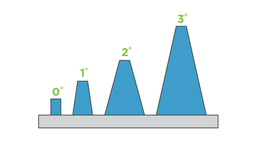
Applying draft and radii to a part is vital to a properly designed injection-molded part. Draft helps a part release from a mold with less drag on the part's surface since the material shrinks onto the mold core. Limited draft requires an excessive amount of pressure on the ejection system that may damage parts and possibly the mold.
A good rule of thumb is to apply 1 degree of draft per 1 inch of cavity depth, but that still may not be sufficient depending on the material selected and the mold's capabilities. Brazil Metal Parts uses CNC milling to manufacture the majority of the features in the mold. The result of our manufacturing process drives a unique wall thickness and draft angle based on the end mill that we are using for each feature. This is where our design for manufacturability (DFM) analysis becomes particularly helpful as our software looks at each part feature separately and compares it to our toolset. The design analysis highlights the part geometry where increased draft and thickness may be required.
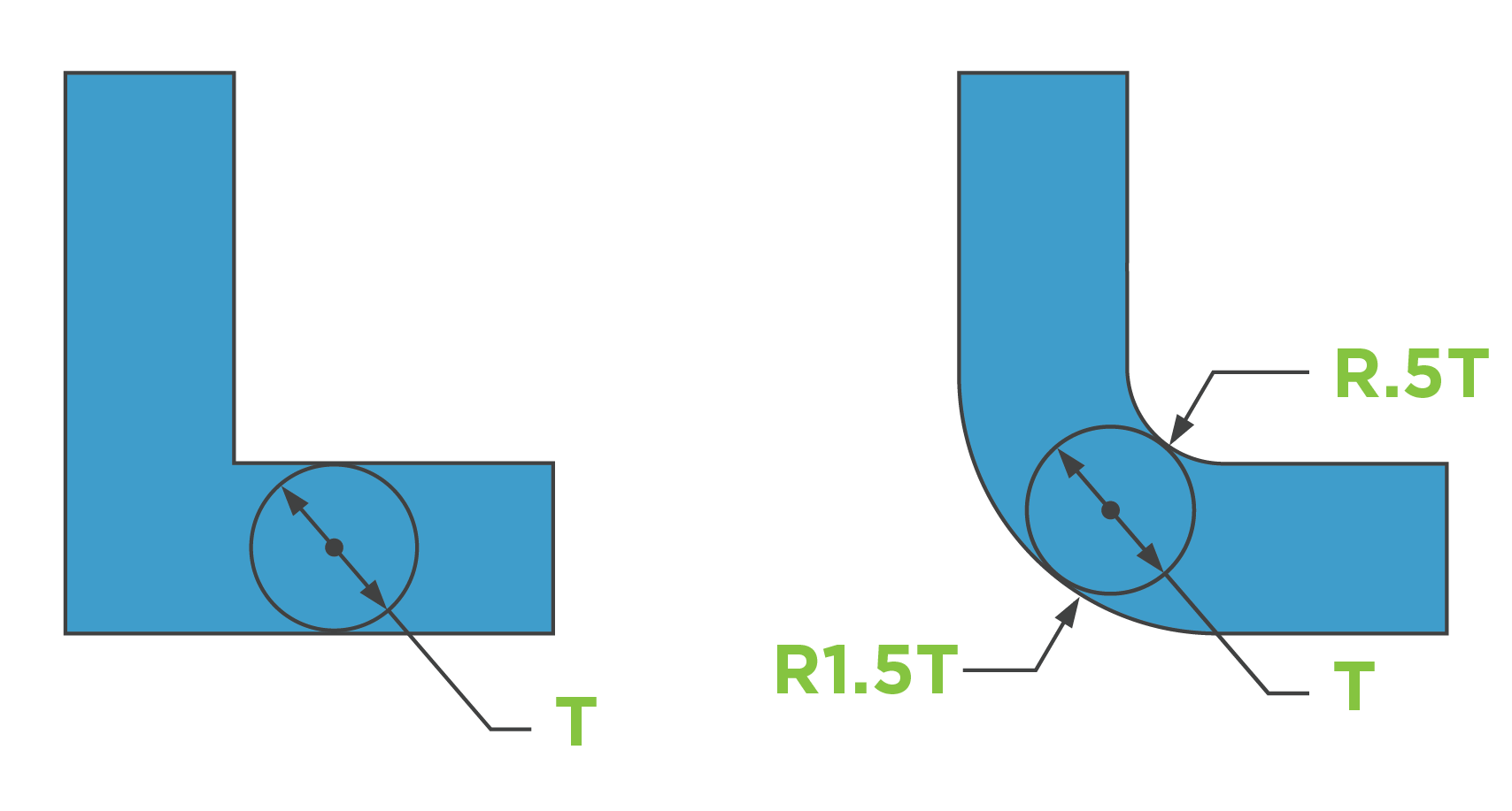
Radii on the other hand isn't a necessity for injection molding, but should be applied to your part for a few reasons—eliminating sharp corners on your part will improve material flow as well as part integrity.
The resin filling the mold cavity flows better around soft corners much like the flow of a river. Rivers don't have 90 degree corners as the water flow creates inside and outside corners so it moves easily towards its final destination. Similarly, plastic resin wants to take a path of least resistance to minimize the amount of stress on the material and mold. Radii, like draft, also aid in part ejection as rounded corners reduce the chance that the part will stick in the mold causing it to warp or even break.
The Importance of Wall Thickness
Controlling wall thickness during part design helps manage cosmetics, weight and strength of your part. Parts that are too thick result in unsightly sink, warp and internal voids (pockets of air). To avoid this, materials have recommended wall thickness guidelines—remember this is only a general rule as not all parts may have wall thicknesses at the high and low ends indicated on the chart.
| Resin | Inches |
|---|---|
| ABS | 0.045 - 0.140 |
| Acetal | 0.030 - 0.120 |
| Acrylic | 0.025 - 0.500 |
| Liquid Crystal Polymer | 0.030 - 0.120 |
| Long-fiber reinforced plastics | 0.075 - 1.000 |
| Nylon | 0.030 - 0.115 |
| Polycarbonate | 0.040 - 0.150 |
| Polyester | 0.025 - 0.125 |
| Polyethylene | 0.030 - 0.200 |
| Polypropylene Sulfide | 0.020 - 0.180 |
| Polypropylene | 0.025 - 0.150 |
| Polystyrene | 0.035 - 0.150 |
| Polyurethane | 0.080 - 0.750 |
Coring Out and Ribbing
Along with employing proper wall thickness, additional considerations should be looked at to ensure a part's design integrity remains intact. One may assume that the thicker the part, the stronger the part—this is a false assumption. A properly designed part that is intended to be structural should contain ribs and supporting gussets, which increase strength and can help eliminate cosmetic defects like warp, sink, and voids.
Let's begin by coring out your thick part, which will still retain the overall height and diameter of your part without necessarily sacrificing performance. There's a good chance you'll increase the part's performance and cosmetic appearance, too.
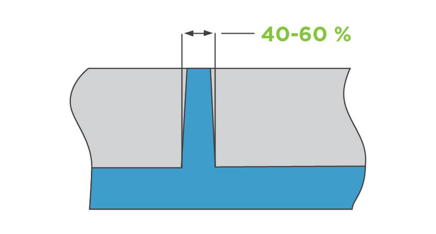
Next, we'll focus on the design of the support ribs. The ideal way to design ribs is by using a rib-to-wall thickness ratio of 40 to 60 percent the thickness of adjacent surfaces. The main body of the part should be designed thick enough so any adjacent rib extruded from it is about half of the thickness. This helps you avoid thick sections that may cool at different rates than the thin sections. It also helps in reducing sink and stresses that can create warp in your part.
Ramps and gussets are yet another design element to strengthen and cosmetically improve your part. Again, plastic prefers smooth transitions between geometries and a small ramp helps the material flow between levels. Gussets help supporting walls or features while reducing molding stresses.
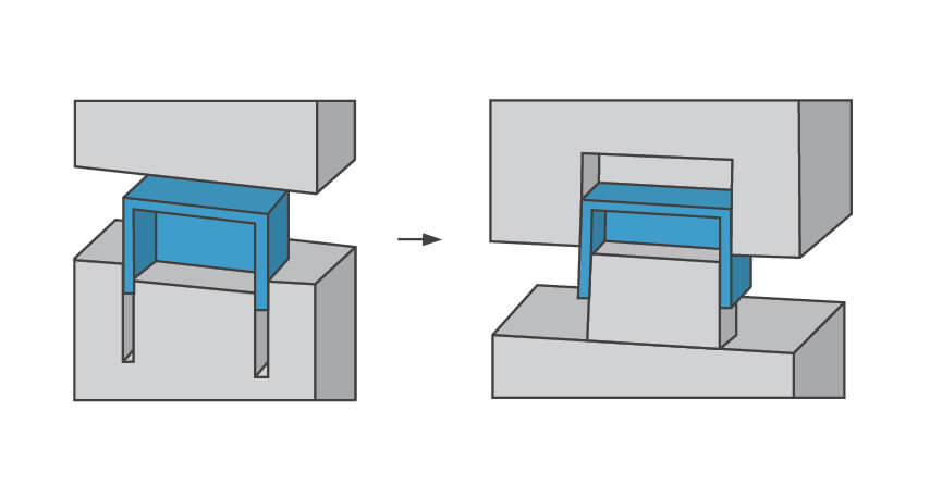
Core-Cavity
The core and cavity are often referenced as the A and B sides or top and bottom halves of a mold. A core-cavity approach to part design can save manufacturing time and money and improve the overall part cosmetics.
Let's say you're designing a simple box. When draft is applied to the outside and inside surfaces in the same mold half, you create a very deep rib that is difficult to manufacture and increases tooling costs. It also increases the chance of mold damage due to difficult ejection and short shots due to lack of mold venting in the deep rib.
You can minimize all of these concerns through a core-cavity approach. This design technique requires the outside and inside walls to be drafted so they are parallel to one another. This method keeps a consistent wall thickness, maintains the part integrity, improves the strength and moldability, and decreases the overall manufacturing cost.
Undercuts
Shunjing injection molding requires that your part design should be as simple as possible, right? This is another false assumption as we support complex part designs that requires undercuts, through holes and other features.
External undercuts are the easiest and most cost effective as we accommodate through pin-actuated side-actions. These side-actions move in tandem with the mold when it is opened and closed while the cam rides along an angled pin. When opened, the cam is fully retracted so the part can be easily ejected without mold damage and closes again till the cam is in position to create the next part.
In cases that are not adaptable for side-actions, we can use manually removed inserts. These are mold components that are greater than a half-inch cube and are loaded by an operator into the press before it closes. After the part has been molded, the part is ejected along with the insert. The operator then takes the part and manually removes the insert and places it back into the mold for the next part.
Gating and Ejection
Gating and ejector pins are a necessity for plastic resin to strategically enter the mold and plastic parts to effectively be ejected from the mold. We've learned from experience that there are several ways to gate or eject your part, and the locations should be considered before you are ready to proceed with tooling.
Tab gates are most commonly used as they offer a mold technician the optimal processing capabilities and have the ability to be increased in size if the process requires it. A tab gate is tapered down in size from the runner, so the smallest point is at the part's surface. This allows a freeze point between the part and runner removing the heat from the surface of the part. You want the heat removed from this surface to minimize any risk of sink in the part. After molding, the tab gate needs to be manually removed leaving a gate vestige within 0.005 in.
Sub gates are generally used by incorporating a tunnel gate into the side of the part or into an ejector pin (post gate). Both gate styles generally can decrease the size of the vestige left on the exterior of the part. Tunnel gates still enter the part externally, but are mid-way down a parts surface, so they typically leave less of a gate vestige. Post gates leave no visible vestige on the exterior of the part as the part fills through one of the ejector pins close to the perimeter of the part. The risk is the cosmetic shadow left on the opposite side of the part due to heat and part thickness. So, be cautious when using this for highly cosmetic parts that have texture or a high polish.
Hot tip gates work well as they have minimal part waste from sprue and runner systems. A hot tip is best for parts that require a balanced fill from the center to the outside edges. This minimizes any mold shift as tab gates can create an unbalanced pressure in a mold. Hot tip gates are often the most cosmetically appealing gate (about 0.050 in. diameter) and often times can be hidden in a dimple or around a logo or text.
Direct sprue gates are the least appealing and are used with specific materials that have a high glass content or where the middle of the part requires secondary machining. Direct sprue gates have a large diameter that is difficult to manually remove and often times require a fixture that is removed by milling.
Technical Help
With a solid grasp of the techniques to improve part moldability, it is much easier to move into low-volume, and eventually high-volume injection molding. The next step is to upload your 3D CAD model online where you'll receive an interactive quote with free DFM analysis within hours. As we said earlier, the DFM analysis will highlight any moldabilty issues and even suggest solutions. We recommend pairing that design feedback with a conversation with one of our experienced applications engineers who will help with any further guidance you might need before production begins. They can be reached at +86-755-29729151 or [email protected].